Ubiquiti Home Network: Part.2
Published Date: 28-NOV-2020
What are you setting up?
Following on from the physical setup in "Part 1", this post will detail setting up the VLANs required to achieve the following:
-
A VLAN for the users in the main house. This VLAN can go out to the internet and also access specific services from another VLAN. This VLAN is going to be VLAN30.
-
A VLAN to sandbox the corporate work laptop. This VLAN can only go out to the internet. It cannot access any other VLANs. This VLAN is going to be VLAN50.
-
A VLAN for myself and my LAB. This VLAN can go out to the internet and be accessed for specific services by other VLANs. This VLAN is going to be VLAN20.
-
A GUEST WiFi for visitors to the house. This WiFi setup can go out to the internet... and that's it. No access to other VLANs or local addresses. This is going to be a WiFi setup on the UAP.
Why?
Again, mostly security. The corporate laptop probing the local network was a big part of buying and setting up my network stack with the capability of sandboxing devices when required. Better to have a setup that's capable and not need to, than one that can't defend you when you need it to.
Overview
A review of our setup (updated version of Part 1), VLAN configuration needed across the EdgeRouterX, EdgeSwitch10XP and the Unifi AP AC Lite devices:
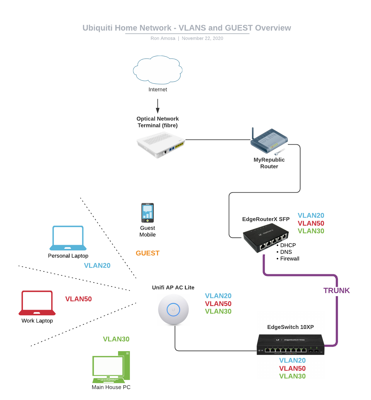
The 'MyRepublic' router is temporary as I setup & configured the network without disrupting the existing internet connection for the rest of the house. Once its all go, the ONT will go directly to the EdgeRouter X.
EdgeRouter X
The EdgeRouter is the epicenter for all things VLAN, so we setup VLAN 20, 30, 50. Because we are going with a "Router-on-a-stick" setup, all VLANs will be configured on the same Interface (eth1).
VLAN: Router
Log into your EdgeRouterX management UI- if you're following from Part 1 - use https://172.16.1.1.
From the 'Dashboard'
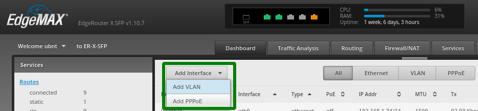
Create VLAN20 which will be my LAB VLAN:
- VLAN ID: 20
- Interface: eth1
- Description: "LAB"
- Address: Manually define IP address (10.0.20.1/24)
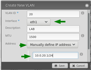
Click 'Save' and you have created VLAN20.
Now, do the same for VLAN30 and VLAN50:
-
VLAN ID: 30
-
Interface: eth1
-
Description: "DMZ"
-
Address: Manually define IP address (10.0.20.1/24)
-
VLAN ID: 50
-
Interface: eth1
-
Description: "SECURE"
-
Address: Manually define IP address (10.0.20.1/24)
When complete, you should have these three VLANs showing:
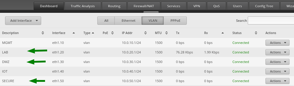
Ignore the other VLANs and just refer to VLANs 20, 30, 50 for this post. I have some work to do setting up the other VLANs for their specific use.
DHCP Servers
We need to setup DHCP servers for each VLAN network so devices plugged into these VLANs will be provided an IP Address from the correct network range.
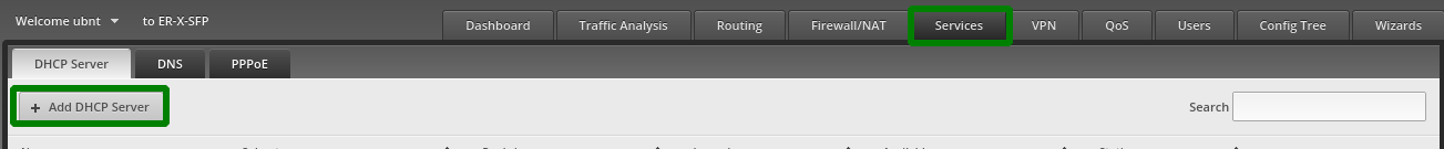
Back in the EdgeRouterX, we want to go to 'Services' -> 'DHCP Server' and click '+ Add DHCP Server'.
Fill in the DHCP Server details for the VLAN20 network:
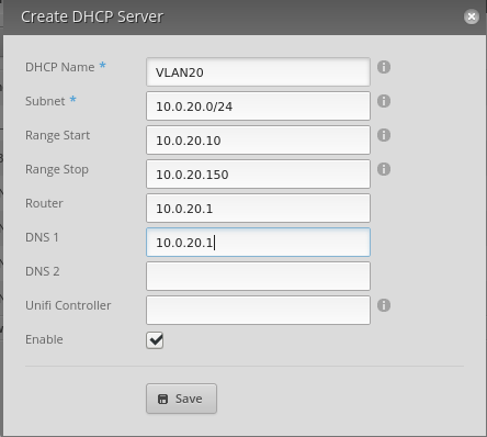
Click 'Save'.
Now do the same for VLAN30, VLAN50
-
DHCP Name: VLAN30
-
Subnet: 10.0.30.0/24
-
Range Start: 10.0.30.10
-
Range Stop: 10.0.30.150
-
Router: 10.0.30.1
-
DNS 1: 10.0.30.1
-
DHCP Name: VLAN50
-
Subnet: 10.0.50.0/24
-
Range Start: 10.0.50.10
-
Range Stop: 10.0.50.150
-
Router: 10.0.50.1
-
DNS 1: 10.0.50.1
Once that's complete, we need to configure one more thing on the EdgeRouterX- DNS Fowarding.
DNS Forwarding
To avoid the issue I ran into from Part 1, we need to enable 'DNS Forwarding' for any interface that we want to allow resolving DNS out to the internet.
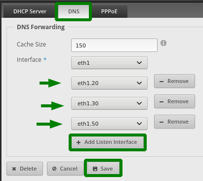
In the EdgeRouterX management UI, we want to go to 'Services' -> 'DNS' and click '+ Add Listen Interface'.
Select VLAN interface eth1.20 from the drop-down menu and then click 'Save'
Keep adding interfaces until your setup looks like this:.
EdgeSwitch 10XP
Next up is the switch. Now that we've created our VLANs we have to make sure every device that we want to involved with the VLANs are configured correctly so they deliver packets where they need to go.
And that means we need to know about Access Ports, Trunk Ports, Tagged, Untagged and excluded ports (we'll learn about them as we go).
Access Port: "a port that can be assigned to a single VLAN. The frames that arrive on an access port are assumed to be part of the access VLAN. This port type is configured on switch ports that are connected to devices with a normal network card, for example a host on a network."
Login to your EdgeSwitch10XP
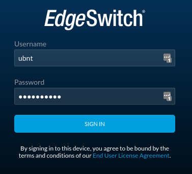
default username/passwd = ubnt/ubnt
From "Part 1" we can see the only 2 ports we're currently using are Port 1 and Port 8.
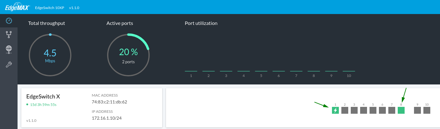
- Port 1 is PoE-enabled port for our UAP WiFi device
- Port 8 is our Trunk Port.
Trunk Port: "a port that is connected to another switch. This port type can carry traffic of multiple VLANs, thus allowing you to extend VLANs across your entire network. Frames are tagged by assigning a VLAN ID to each frame as they traverse between switches."
From our digram from before:
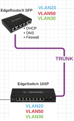
the connection from EdgeRouterX port eth1 into EdgeSwitch10XP needs port 8 to be a Trunk Port to understand that it has to handle multiple VLANs that arrive on that port.
VLAN: Switch
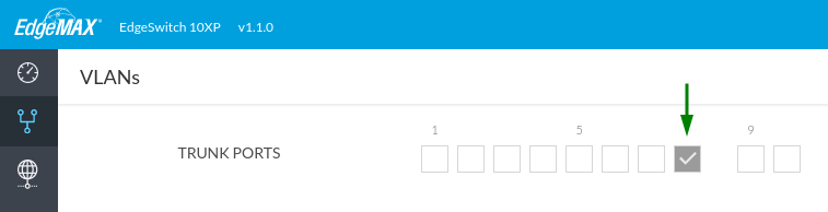
Click the 'VLAN' link in the side menu.
First, un-check all the ports in the 'TRUNK PORTS' section, and check only Port 8
Next, go over to the text field to add a VLAN

enter 20, 30, and 50 to create those VLANs.
Tagging, Untagging VLANs
The setup uses 802.1q VLAN tagging protocol to tag Ethernet frames (i.e. network data packets) so the packets know which VLAN they're going to and coming from.
Tagging - when you "tag" a port by setting it to 'T' on a particular VLAN row, it means that port is set to recognize that VLAN ID (e.g. VLAN ID: 20 "LAB" on port 8). The "tag" is an 802.1q header that the network device adds to the frame to mark that packet as being part of that VLAN.
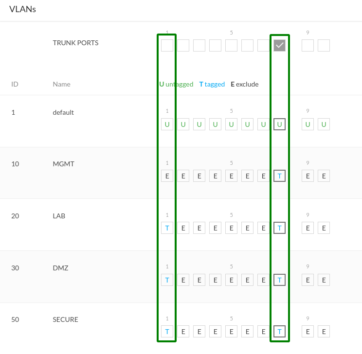
The setup only has 2 x devices connected, so only ports 1 & 8 will have 'T' tags for the VLANs we want handled by those ports.
Untagged - is a little bit tricker to explain, but essentially on any given VLAN capable network device is a "native VLAN". When a port receives a frame (network packet) that is "Untagged", i.e. it just doesn't have the extra 802.1q field, it assumes the frame is part of the native (default) VLAN and sends it there. This is why its important for both devices to agree on the native VLAN.
As you can see in the diagram, the 'default' VLAN (ID:1) is set to 'U' or "Untagged" for ports 1 and 8.
One thing to keep in mind is that some management level communication happens between devices and default to the native VLAN (ID:1), so if you don't ensure the 'U' is on a default VLAN ID that matches other devices, you're going to have a bad "why is the connection timing out?!" day.
To summarize:
Port 8: Trunk Port (uplink)
- set (T) on vlans 20,30,50.
- set (U) on 'default' VLAN (ID=1).
Why? This port needs to recognize these VLANS so it can deliver frames coming down from the upstream device to ports other ports on this device.
Port 1: AP
- set (T) on vlans 20,30,50.
- set (U) on 'default' VLAN (ID=1).
Why? This port is connected to the Unifi AP where we will have VLANs setup on multiple SSIDs, so this port needs to recieve and deliver multiple VLANS from the AP to the switch, and from the switch to the AP.
Now to setup the last device- the Unifi AP AC Lite.
Unifi AP AC Lite
Note: firmware at time of writing: UI: 6.0.28, Backend: 6.0.28, Build: atag_6.0.28_14280
Log into your Unifi network controller (see 'Part 1' for setting up and logging into the unifi network controller).
Networks - LAB, DMZ, SECURE
Once logged in, have a quick look at your AP and see that it's working (presumably)
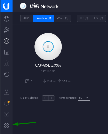
Click on the 'cog' which takes you to your 'Settings'
Click 'Add a New Network' button
![]()
Setup the 'LAB' network first- this is the network where my lab servers and devices live; devices in this VLAN can go to other VLANs, but other VLANs have limited access to here:
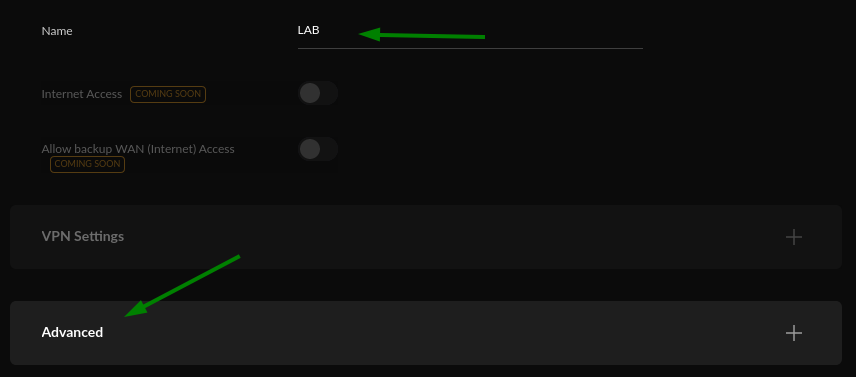
Enter "LAB" in 'Name' or whatever name you want
Then click 'Advanced'
Under 'Advanced' settings you want mainly the following 2:
- VLAN ID = '20'
- DHCP Mode = 'None'
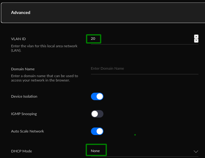
Setting up the 'Domain Name' is on the To-do list
Click 'Apply Changes' and you are done (for this Network)

Now, repeat this step for
- DMZ Network (VLAN ID: 30)
- SECURE Network (VLAN ID: 50)
Your Networks page should look similar to this after:
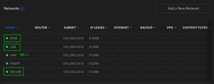
Note: the 'LAN' network is a preset default and locked to the default VLAN.
Networks are setup, now they need WiFi's attached to them.
WiFi - LAB, DMZ, SECURE
These steps are pretty straight-foward now the Networks are set up.
Click 'Add New Wifi Network'

And setup the 'LAB' WiFi:
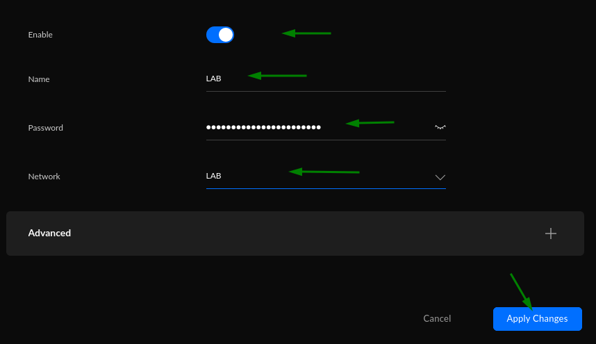
- Enable (checked)
- Name: (anything you want, the maint thing is the Network you pick below)
- Password: (something strong)
- Network: LAB (choose from drop-down)
- Advanced: leave to defaults
Click 'Apply Changes'.
Again, repeat these steps for a 'DMZ' and 'SECURE' WiFi.
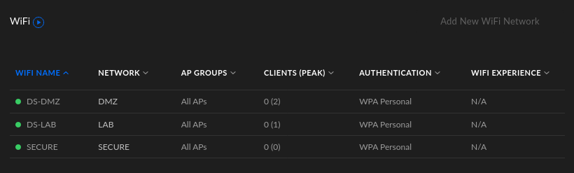
Your WiFi list should look like this after:
Guest Hotspot
The 'Guest Hotspot' is a little special in that we create it from it's own special wizard below the WiFi's we created.
Click 'Add New Guest Hotspot'
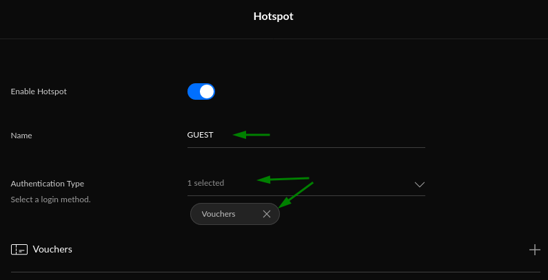
I chose 'Vouchers' Authentication Type for fun (my wife doesn't think its funny :D), where in the Hotspot Manager (I'll show you later) you get a list of voucher serial-numbers you can hand out to guests and they only last for a set time (change this under the 'Advanced' section).
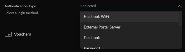
There's a bunch of other Authentication types to keep things interesting:
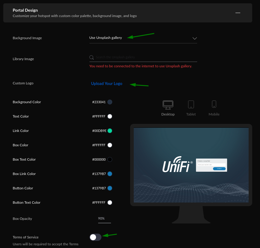
There's also this cool 'Portal Design' section of the Guest Hotspot where you can set a background image, logo and color scheme, display 'Terms of Service' for your Guest login page
One important setting under 'Advanced' to be familiar with is the 'Restricted Authorization Access'
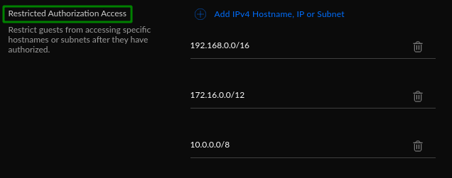
This setting lists the 3 x main internal/local network ranges (add more if you want) and restricts Guest Hotspots from being able to connect to these ranges, which is what you want.
Click 'Apply Changes' button and you have the GUEST WiFi (Hotspot) set up.
Note: You can only have a MAXIMUM 4 x WiFi(SSID) including Guest Hotspots. Your 'Add' buttons will grey out when you reach MAX.
You should see the new WiFi/SSID's are available and be able to connect to them.
That's it for Part 2!
In the thrilling conclusion to this 3-part series, we will setup our Firewall rules and rulesets to properly secure things off and that should be our basic Ubiquiti Home Network with VLANs complete!